WS2812 LEDs are amazing devices – they combine a programmable constant current controller chip with a RGB LED in a single package. Each LED has one data input and one data output pin. By connecting the data output pin to the data input pin of the next device, it is possible to daisy chain the LEDs to theoretically arbitrary length.
Unfortunately, the single-line serial protocol is not supported by standard microcontroller periphery. It has to be emulated by re-purposing suitable hardware or by software timed I/O toggling, also known as bit-banging. Bit-banging is the preferred approach on 8 bit microcontrollers. However, this is especially challenging with low clock rates due to the relatively high data rate of the protocol. In addition, there are many different revisions of data sheets with conflicting information about the protocol timing. My contribution to this was the light_ws2812 library V1.0 for AVR and Cortex-M0, which was published a while ago. A V2.0 rewrite of the lib was in order due to various reasons. And, to do it right, I decided to reverse engineer and understand the WS2812 LED protocol to make sure the lib works on all devices.
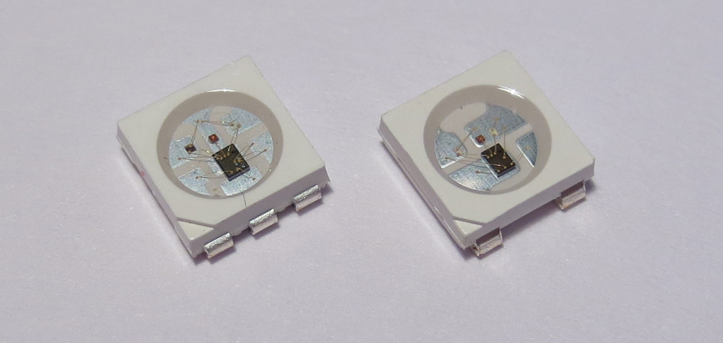
As of now, there are two different revisions of the WS2812 on the market: The original 6 pin WS2812(S) and the newer 4 pin WS2812B. The data sheets can be downloaded from the website of world-semi, the original manufacturer, here and here.

The data transmission protocol itself is relatively simple: a digital “1” is encoded as a long high-pulse, “0” as a short pulse on “Din”. When the data line is held low for more than 50µs, the device is reset. After reset, each device reads the first 24 bit (GRB 8:8:8) of data into an internal buffer. All consecutive bits after the first 24 are forwarded to the next device go through internal data reshaping and are then forwarded via “Dout” to the next device. The internal buffer is written to the PWM controller during the next reset.
So far so good. This is where things get confusing. I copied the timing specification from both datasheets above. As you can see, both devices have slightly different timing for the encoding of the “1”. Furthermore, the tolerances for the “data transfer time” are completely different and are in conflict with the “voltage time”. So what are the real tolerances and can we find a set of timing parameters that fits both devices?
Luckily there is a relatively easy way to probe the inner workings of the device: When data is forwarded, it is passed through the internal reshaping mechanism. Therefore we can exercise Din and verify the correct interpretation of the input data by comparing it to Dout. To do this, I hooked a single WS2812 to a ATtiny 85 which took the role of a signal generator. I then monitored both Din and Dout with a Saleae logic analyzer. There are some issues with aliasing, since the maximum sampling speed is only 24 Mhz, but the data seemed still sufficient to understand the WS2812.
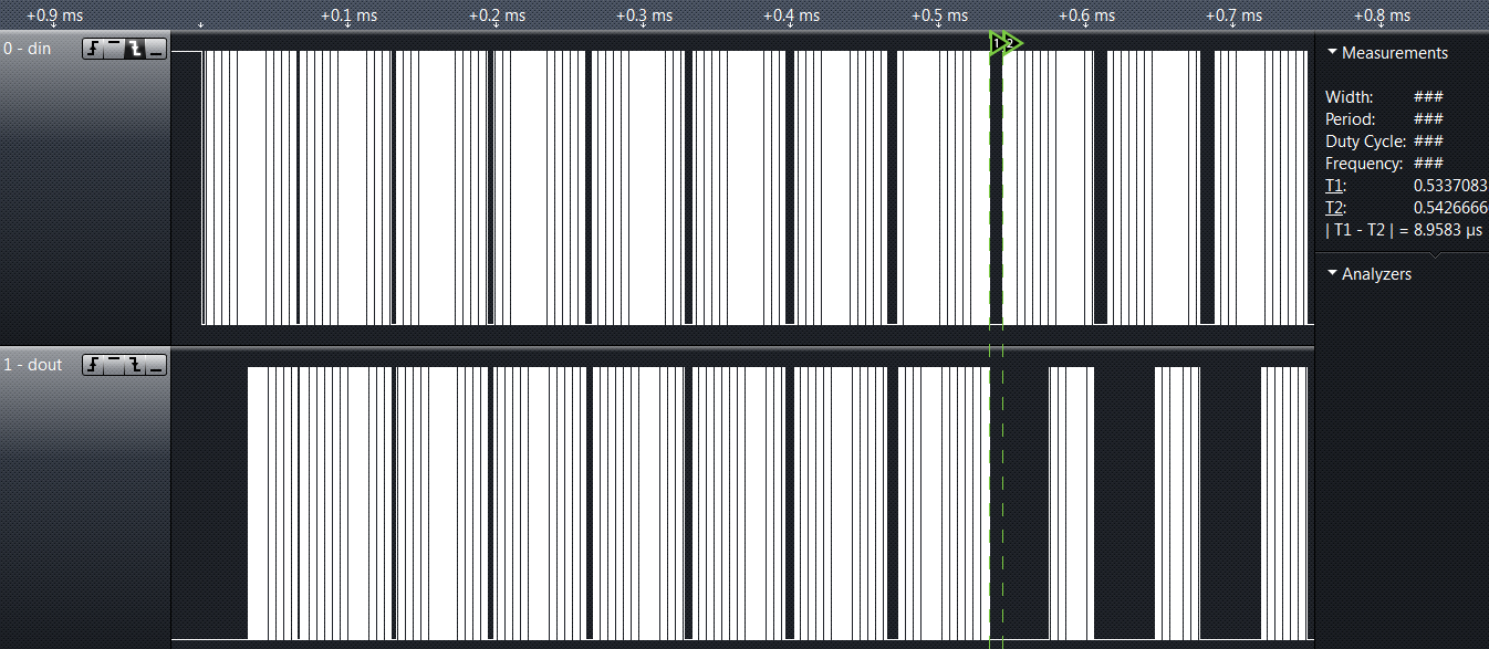
In my first experiment I tried to determine the minimum time needed to reset the LED. My program emitted blocks of 48 bits with increasing delay time in between the blocks. As you can see above on the left side, all input data is forwarded to the output if the reset delay is too short. Once a certain delay threshold is reached, a reset is issues and data forwarding will only start after the first 24 bits, as seen on the right side. For the WS2812 under test here, the minimum reset length was 8.95 µs, way below the specifications. The suggested reset time of 50 µs is therefore more than sufficient to reset the LEDs. On the other hand, it means that no more than 9 µs of idle time may occur during data transfer, or a reset may mistakenly be issued.

In the next step I looked at the data timing itself. The image above shows an exemplary measurement of input and reshaped output waveforms. Both waveforms can be described by two parameters each: The duration of the hi pulse and the total period. I programmed the microcontroller to cycle through all possible pulse input combinations between 62.5 ns (1 CPU cycle at 16 MHz) and 4 µs with a granularity of 62.5 ns. You can find the code is here.
My original intention was to perform an automatic evaluation of the captured data to create a shmoo plot. However, I quickly noticed that the behavior was quite regular and instead opted to analyze the data manually.
One of the first observations was that the delay between the leading edge of the input pulse and the leading edge of the output pulse, T_delay_in_out, was constant regardless of the timing of the input pulse.

The image above shows a variation of T_hi_in for a constant T_period_in. The period length, called total data transfer time in the datasheet was set to the specification value of 1250 ns. As is obvious, there are only two states of the output signal: A short pulse for a “0” and a long pulse for a “1”. Even the shortest input pulse (62.5 ns) is identified as “0”, while even the longest input pulse (1250-62.5=1187.5 ns) is identified as a “1”. The threshold between “0” and “1” is somewhere between 563 and 625 ns. The LED brightness changes accordingly, suggesting that the observations from the output signal are indeed consistent with the internal state of the LED.

Next, I varied T_period_in. When the period time of the input signal was much shorter than 1250 ns, the WS2812 started to reject input pulses. As can be seen for 333 ns, only about every fifth input pulse is replicated in the output pulses. The shortest pulse period time where all input pulses appeared on the data output was 1063 ns. Below that the input pulses were partially or fully rejected. Above this threshold all input pulses were interpreted correctly and the period of the output signal reflected the period of the input signal up to 9 µs when the reset condition was met.
This is an interesting observation, because it means that while there is a strict lower limit for the period time of the input signal, there is no real upper limit. For practical purposes, this allows relaxed timing in the software driver.

The table above summarizes my findings from the WS2812 and WS2812B each. It is possible that there are significant differences between production batches of both types, therefore these number can only serve as a rough indication. All timings seem to be a bit shorter on the WS2812. This is consistent with the data-sheet which indicates a longer pulse time for the “1” on the WS2812B.
An interesting observation is that the timing values for both LEDs are multiples of a smaller number, ~208 ns for the WS2812B and ~166 ns of the WS2812. It appears that the internal controller circuit is actually a clocked design – possibly realized by a small state machine.
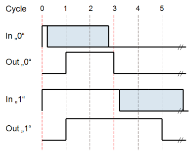
This becomes much more obvious with the diagram above, which normalizes the timing to “WS2812 cycles”. The internal WS2812 state machine only needs to sample the input twice per bit: First, it waits for a rising edge of the input. This will initiate the sequence above. The input is latched again after cycle 2. The voltage of the input pin at this point determines whether a ‘1’ or a ‘0’ is read. Depending on whether the LED already has received 24 bits or not, this value will either be loaded into an internal shift register or decide whether a 2 or 4 cycle ‘hi’ level signal is emitted. The sequence ends after cycle 5 and repeats again with the next rising edge.
So, what did we learn from this?
- A reset is issued as early as at 9 µs, contrary to the 50 µs mentioned in the data sheet. Longer delays between transmissions should be avoided.
- The cycle time of a bit should be at least 1.25 µs, the value given in the data sheet, and at most ~9 µs, the shortest time for a reset.
- A “0” can be encoded with a pulse as short as 62.5 ns, but should not be longer than ~500 ns (maximum on WS2812).
- A “1” can be encoded with pulses almost as long as the total cycle time, but it should not be shorter than ~625 ns (minimum on WS2812B).
Next part: Optimized “Bit-Banging”

The only thing I’m curious or surprised about is that you can’t pack the short bits closer together than the long bits, that the period has to be >1250 for both. I.e. that the low time has to be the opposite length.
Yes, that surprised me too. But on the other hand it provides some level of robustness towards glitches. I don’t think this behavior really adds complexity to the state machine.
My guess is that there are few (4 or 5) simple RC pulse generators that take care of the timing.
From my observiations I believe it is a clocked design. That makes a lot of sense, since RC oscillators take up a lot of area on the chip.
Thanks for this investigation cpldcpu. The WS28xx datasheets are quite poor, so it was nice to find some more in-depth testing.
I have a fairly dumb question, but one I haven’t seen answered anywhere. I’d like to design a bicycle-wheel POV thing with some of these LEDs, and I haven’t been able to tell what happens when the string is reset. Do all of the LEDs go dark, and then turn back on, one at a time, as the new data is clocked in? Or does each LED retain its previous state until the new data reaches it? As you may imagine, the distinction is make-or-break for a POV project.
The LEDs are updated almost instantly after a reset without a blanking period.
However, you should note that the WS2812 is PWM based with a frequency of roughly 400 Hz. There is visible flicker when moving the LEDs quickly. In a POV application you are probably limited to maximum and minimum brightness to avoid the “dotted line” problem with PWM.
Oh wow, I can’t believe I didn’t come across that little detail (PWM) in the datasheet or anywhere else online! That completely rules it out for my application. Guess I’ll have to keep looking.
It’s now a few years later, but for that lone soul that comes here wondering about this, look into APA102C LEDs, they have a _much_ higher internal PWM rate (~20MHz) and work well for POV displays.
A very nice post.
Want to see over 3000 WS2812s working with a single micro and without any bit bashing ?
Take a look at http://www.youtube.com/watch?v=6sJH7wv0Lg8
and http://www.youtube.com/watch?v=8dYcjvWnKQo
Nice! For some reason Cypress really seems to like the WS2812. They also had some on display on their booth at EW2014.
No bits are bashed anywhere, though!
Big thanks for this useful post.
I’m working on ws2811 using this post and I want to drive it. I would like to know is there any problem if I use read my RGB colors data from a MMC. I want to store my lighting effects to a MMC and read them by AVR and send data to a ribbon of 5050 leds are driven by ws2811.
I know how to read MMC by AVR and how to send data to ws2811 but I want to know if it is fast enough and is it possible at all?
Please help me to do this.
You have to store the data in the SRAM intermediately, you cannot read from the MMC and write to the WS2811 at the same time, as the MMC my cause delays that are too long for the WS2811.
thanks for your reply.
This process, reading data from MMC and write to SRAM and then send to ws2811 as data takes time. Dose not this time (delay) cause problem? I have a ribbon including 700 leds and for each color one byte is needed so I must read 700*3=2100 bytes. Reading this 2100 bytes takes time.
yes, it will take some time. 700 LEDs is a lot. You may have to consider a soluation with a more powerful cpu then AVR.
Nice job 🙂
We also needed details on how these modules worked, and ended up with similar work and results. Here is a post about it.
http://hypnocube.com/2013/12/design-and-implementation-of-serial-led-gadgets/
Chris Lomont
Nice! You basically ended up with the same model.
“So, what did we learn from this?”
…That you’re a legend, Tim, for having researched and published this information and those vital four points.
I had been frustrating over these devices for too many hours but thanks to you, I got my little critter to work.
Note for http://www.world-semi.com/en/ : publish a spec’ sheet which is truly useful, not just a ‘guide’.
Cheers and grateful thanks…
You are welcome! 🙂
Yeah, World-Semi is puzzling me. They are messing up the launch of their successor device (WS2821) by not publishing anything about it. But on the other hand, the “maker” business is probably only a small fraction of their revenue, so I can’t blame them…
Hi Tim!
Love your work and how you explain how things works, and your blog is actually where i learn how to drive a 12 led ws2812B ring. What i wanted to do is to find a way to drive this ring with less hardware as possible. I meant if you just want to make a Christmas tree star, there’s no need to hook up your arduino just for that purpose. What i found out was that you can drive you pixels at a VERY low bit rate. I could send one bits every 50 ms(!) without a reset condition. Thats really amazing because if you dont have a long strand and a huge amount of led to drive, then you can drive your leds with ease, no assembler (which is really good to learn) is required.
It works by stressing the logic 1 bits high time as long as you need to get the next bit (bits) and then pull the data line low for a new bit to start again. Not a elegant solution, but i just want to show that its possible to prevent a reset to occur if you need to wait (lets say more than 10us) for new data.
Hi,
yes, this makes a lot of sense and agrees fully with the behavior of the LEDS as described above. If you want really small code to drive the WS2812 you can use my lib: https://github.com/cpldcpu/light_ws2812
Thank you so much for this spot on analysis. I like that you reverse engineered the state machine. I’m imagining the internal oscillator could change frequency with heat, or with manufacturing variations, which could change the timing figures.
The fatal flaw in the WS2812 design, from my perspective, is that the reset timeout is so short. It is shorter than a typical timer interrupt period, which makes it difficult to service these LEDs in a system with concurrent processes.
The chip I’m using doesn’t have DMA, but it has a 16 bit data register on the SPI. So what I reckon is, set the SPI bit period to 500 ns (2MHz clock), so it takes 8us to shift out the 16 bits. If you add the 9 us before reset, that makes a minimum period of 17 us. Too short for a timer interrupt I would say, the MCU would be bogged down by interrupt overhead.
So…write 16 bits to the SPI at the start of the timer interrupt, do everything else that needs to be done, then at the end of the interrupt write another 16 bits. That will require some tweeking, as the interrupt handler execution period must be 8 us. And if the other processes could take longer than 8 us, polling of the SPI ready status would need to be interleaved. Assuming this concept works, the timer interrupt period would be 25us. That is feasible, in fact that is what I am using at the moment.
Yes, in many cases using the periphery will not relax the CPU time requirements by much. As unelegant “Bitbanging” may look, it is often the lesser of two evils…
FANTASTIC post. Thank you!
Hi – very nice work! I am just playing around with your arduino code and some 5 meter of 2812b strip with 60 LEDs/meter. This gives me a total of 5*60 = 300 LEDs on one strip. However, I am only able to power 255 LED’s along the strip using your git code for “fade_rgb”. When I try compile and upload with 256 LEDs in total, the Arduino doesn’t turn ANY LEDs on at all. Going back to 255 in the code again works just fine… In an attempt to troubleshoot it, I tried to change the “#define LEDCount 256” to “int LEDCount = 256;”, since the int type should be 16-bit according to the references, but it still doesn’t work 😦
Do you have any idea why I can’t power on more than 255 LEDs using your code? I am on Arduino UNO.
(5V DC is supplied to both ends of the strip using a 10A adapter, and nothing seems to be wrong with the brightness of the individual LEDs, so I’m quite sure the circuit is not missing juice.)
This looks like a bug in line 37 of the example. I changed it on github. Can you test it? Thanks,Tim.
Works like a charm!

By the way, in your code, for this “fade_rgb” example, the green and red properties are switched around. This means that the following code sets the intensity for the green colour and not the red. And vice versa. Blue is fine 🙂
value.b = 0;
value.g = 0;
value.r = intensity; // RGB Value -> Red Only
I am currently switching between your code and the FastLED library, and it seems like the emitted colours are not flickering as much with your code. Have you compared this aspect as well? I am going to do some more comprehensive testing when it gets dark (it’s morning now:)
Hi Tim
Congrats!! good job thank you
I have some questions
1- Suppose i have 3 cascaded Leds. after resetting the controller and then sending a 3×24 bit (i.e. 3 frames one for each led) do i need to reset the controller to update the led state or the leds are updated when they receive each frame?
2- Do i need to refresh continuously or can I stop sending for a long time and last data is held until next sending. For example sending 3 frames and holding DIN at “1”
Thanks
Daniel
1) The LEDs are only updated after the reset condition is met.
2) Yes, that should work, but I have never tried.
Many Thanks Tim
Daniel
Hi Tim
I’ve a question: Sending a bit to the WS2812 this means setting DIN hi for T0H ns for a ‘0’ or T1H ns for a ‘1’ and then send a zero until the period is reached. Once reached this point may i held the DIN low for a while before sending next bit? I’m asking this after watching your code:
ldi %0,8 Loop 8 times for one byte
loop:
out %2,%3 // [01] – t0 Set output Hi
…wait1…
sbrs %1,7 // [02/03] – Skip t1 if bit 7 is set
out %2,%4 // [03] – t1 Set output Low
…wait2…
lsl %1 // [04] – Shift out next bit
out %2,%4 // [05] – t2 Set output Low
…wait3…
dec %0 // [06]
brne loop // [08] – t3 Loop
it seems that after sending 8 bits the DIN pin stays low for a while and you made a comment at the end i quote it:
“The outer loop is implemented in pure C, since it can be safely assumed not to take more than 5 µs.”
Does this mean that i can stop sending bits at any time letting the DIN low
for a while ( To take a breathe 🙂 ) and then continue sending bits?
Is this “5us” a WS2812 limit or just a value selected to have a reasonable throughput
Thanks in Advance
Daniel
Yes, you can. But if you wait for more than 5µs it will be interpreted as a reset.
Hi cpldcpu,
Very nice blog about driving the ws2812 LEDs. I’m trying to implement your code and would like some advice.
I want to drive ~140 ws2812b LEDs in my quadcopter, reacting to RC commands. It is controlled by a Naze32 controller which has an ARM based 32bit Cortex-M3 STM32F103 chip running Cleanflight firmware. Currently it uses a DMA buffer and it can only drive 32 LEDs due to RAM constraints. Do you think it is possible to use your code in the background while running the stabilisation algorithms?
https://github.com/cleanflight/cleanflight
Thanks!
Hi Tim,
great job and lots of useful advices. A have some question for you about my project, based on WS2182. I started with Atmega8 with 16mhz osc. and wrote succesfully an efficient PWM generator for 24 bitmap. I reached times for LOW signal 0,33us, HIGH signal 0,83us but the total period is a bit longer than it should be and is about 1,4-1,6us. I have also very small additional gaps between every 8-bit package about 0,2us. As you mentioned the period time resulting in ‘reset’ is about 7 us and I got the same for simple tests. The problem appeard when I started displaying infinite loop in code. The signal looks OK, image is visible on LED screen but I must apply very long reset signal about 3 ms(!) otherwise I could see more and more vanished points. Some pixels start to blink randomly near 1ms. That’s far far away from 7us. Is the problem with LED internal clock and my signal synchronization? Thanks! (and sorry for my english 🙂 ) ,Mark
That sounds very odd. It could also be an “analogue” problem.
Have you checked if your current supply is sufficiently powerful? Is your signal free from noise and distortion?
DUDE your library drastically reduced the memory footprint on my ATTINY85 and it also runs fast enough to let me do Serial debugging, where the Adafruit lib couldn’t keep up and the LEDs would die. You rock!
thanks!
>There are some issues with aliasing, since the maximum sampling speed is only 24 Mhz…
>An interesting observation is that the timing values for both LEDs are multiples of a smaller number, ~208 ns for the WS2812B and ~166 ns of the WS2812….
Hm…maybe, but 208ns is about five 24MHz cycles and 166ns is about four. It is a common oscillator frequency though, and a multiple of 12/8/etc.
Also, thanks so much for writing this, it was really helpful and thanks to you I got the protocol working with a 12MHz clock on an FPGA. Four groups of four 83.33ns cycles per bit 🙂
Interesting article, thanks for sharing. The pathetic datasheet for the WS2812 doesn’t seem to indicate it anywhere, but do you think this device has a „memory“ of its last color value, after powering it off? From what I’m seeing, even if I disconnect the strip completely from power, then power it back up, it turns on with each pixel showing the last color I wrote to it. That’s surprising to me. Are you aware of any documentation that might address this?
Fascinating read, thanks!
Thanks a lot for sharing your experiments!
It makes sense that the internal chip is clocked by an internal mechanism, after all, it does have it’s own PWM generator for the LEDs. So there must be a clock generated in there somewhere. Probably fairly fast and divided down, as you stated, RC oscillators take up a good deal of real-estate, which that chip seems to be lacking.