During the last months, a new WS2812 alternative appeared on the market: The SK6812. I finally managed to get my hands on some of them to take a closer look. In most aspects these devices are basically clones of the WS2812. What is interesting however, is that the manufacturer came up with a couple of new variations of the stock 5050 RGB LED.
As with many components from mainland china, it seems very difficult to identify the actual manufacturer of these devices, as vendors tend to rebrand data sheets. It appears that at least one of the original manufacturers is Opsco Optoelectronics. However, it is likely that there is more than one manufacturer is using the SK6812 brand, which does possibly only refer to the controller chip itself. The “SK” prefix, on the other hand, is normally used by Shenzhen Sikewei Electronics, which seems to specialize on speech ICs and similar low-cost applications. Are they connected? No idea…
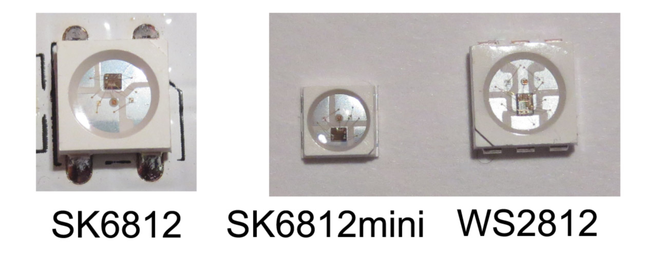
The image above compares the “grandfather”, the WS2812S, with two new devices based on the SK6812 controller. The SK6812 is a direct clone of the WS2812B, while the SK6812mini comes in a smaller package with a 3.5×3.5mm² footprint. This is quite useful, since it allows more dense matrix displays than with the normal 5.0×5.0mm² packages.
Another, less obvious, difference is in the size of the controller IC and LED dies. The SK6812 is actually a bit smaller than the WS2812: Based on a rough measurement, the WS2812 is approximately 0.8×1.05=0.84 mm² while the SK6812 measures 0.6×0.8=0.5 mm². This suggests that the SK6812 is indeed a complete redesign. The smaller chip size should, in principle, also lead to lower cost. Although this depends on the manufacturing technology as well. In the same vein, the SK6812 also uses slighly smaller LED dies. This is most likely another measure to reduce cost.

So, how do these devices behave electrically? I subjected the SK6812 to similar tests as I performed previously on the WS2812 and its variants and clones. The results are summarized in the table above. The timing of the SK6812 is slightly faster than that of the WS2812 (“High” timing is 440 ns vs. 625 ns). However, I don’t expect any issues with the timing of existing WS2812 libraries, such as the light_ws2812 library. An interesting difference is that the PWM frequency of the SK6812 is more than twice as high as that of the WS2812 (1.1 kHz vs. 430 Hz). This should lead to less visual flicker, although the frequency is still not high enough for persistence of vision displays.

The SK6812 uses an identical package to the WS2182B. What is notable about the SK6812mini is that it does not only use a smaller package, but also a different packaging technology. Here, the metal frame, that is used to mount the dies in the package, also serve directly as solderable contact, as shown in the image above. In principle this should allow better heat removal from the LEDs and the controller chip.
However, heat conduction isn’t a one-way process: The SK6812mini seems to be quite sensitive to heat. If it is overheated during (hand-)soldering, white stuff seems to encroach on the lead frame, which ultimately leads to broken contacts. In the device shown below, the red LED in the center stopped working.
Apart from the standard version, the SK6812 also comes in a RGBW version with 4 channels. This adds a white channel to the normal RGB version, which can be used for better color reproduction. This version needs 4 data values per LED. Other than that it seems to be functionally identical to the normal 3 channel controller. I extended the light_ws2812 library to allow controlling RGBW LEDS. Please have a look at the repository for details.
In summary, the SK6812 and its descendants are an interesting variation on the WS2812, most notably the SK6821mini due to its small footprint and the RGBW version. The improvements are mostly evolutionary, however. I wonder what the next big thing in integrated LED controllers will be?

Hi just a question on the soldering teqniuqe for the sk6821 mini.
I cant for the life of me solder these leds without damage,if i set iron too low the solder doesnt melt but still melts the whole led to bits,even tryed hot air still total melt down,is there a solder wich melts at a lower temp?or any tips on how to solder these leds,I wanted the the real ws2812b mini but got sent these leds,chocolate melts at a higher temp than these,ime sure i got a faulty batch made from plastic not heat resist plastic. lol even tryed heating the pcb pads up with solder on and place the led on top but led chip inside goes crack every time. never known anything like it,ive wasted 80 leds without seeing one work properly.do you know where i can get the ws2812b mini leds? thanks
I already used SK6812 on a board and had 80% yield after following mfr recommended soldering. Moreover, they fail if someone bends the PCB accidentally.
I switched to ws2812b MINI 3535 and have no problems so far. Soldering is easy (99.4%)
You can try aliexpress for (ws2812b 3535).
You can try to solder LEDs using lichtenberg’s alloy if it is available in your country. I’m using it for PCB tinning in boiling water because melting point of this alloy is 95-100°C
Use your hand soldering iron at a higher temperature setting (400~410 °C) and very short soldering cycles (<1 s)
Has anybody had success running a PCBA with these lights through an aquoues batch wash? It looks like they should be okay as they are sealed but want to check due to the MSL5a sensitivity.
Thanks!
Do you have any info on lumens output for various LED types? I’m curious about approximately how many WS2812s it takes to be equivalent to a 40W incandescent, for example.
No idea. In principle the could be calculated from the mcd values in the datasheet in connection with the angular characteristics, but I am not sure how correct they are.
I’ve seen some estimates saying it’s about 6.8 lumens per module. A 40W bulb is around 450 lumens, and 60W is 800 lumens. So if that estimate is correct, the combined light of 66 pixels at full brightness is roughly equivalent to the light of a 40W bulb. Or 118 pixels for a 60W (and would consume 19.8W and 35.4W, respectively).
Awesome find – these SK6812mini’s look a lot like WS2852 I found on TME (http://www.tme.eu/en/details/ws2852/smd-colour-leds/worldsemi/) but then a little better.
Do you have any data on the reliability of these smaller chips?
Another thing to note is that the colour sequence of the SK6812 is in standard order (RGB) instead of with the red/green swapped (WS2812 accepts colours in GRB order).
Curious if you know how the luminosity compares to the ws2812b? The specs claim numbers that seem 2-3x the mcd of the ws2812b…
SK6812 5mm pkg
min max avg lumens watts/LED
R 700 1000 1200 3.77
G 1500 2200 2600 8.17
B 700 1000 1200 3.77
total 5000 15.71 0.4 39.27 lumens/watt
WS2812/B 5mm pkg
min max avg lumens watts/LED
R 550 700 900 2.83
G 1100 1400 1800 5.65
B 200 400 400 1.26
total 3100 9.74 0.3 32.46 lumens/watt
NB: SK6812 is 80mA@5v, WS2812B is 60mA@5v, 25% higher power consumption. SK6812 also claims ~20% more lumens/watt, may reflect year to year change in available LED specs or different test method.
Warning: “Your mileage may vary” LEDs are often tested using a short pulse and don’t reflect efficiency lost due to delta Tjc etc. The effect of increased junction temperature in continuous operation is not trivial. Neither manufacturer specifies package thermal resistance.
Nice review. Curiously waiting on a WS2813 review. Are you planning to do that?
I have used the SK6812 mini (3535). it is very sensitive to heat. I have used them to make a matrix at 6x6mm grid. Some LEDs, as mentioned, have one color blown up. When heat gets higher the soldering joint breaks.
I am redesigning with the new WS2812b-mini (also 3535) instead.
Hi Tim,
Do you have any confirmed WS2812B LEDs that you can measure the dimensions of the IC inside?
I’m trying to verify which packages I have and unfortunately they’re all sold to me under the misnomer of “WS2812B”. I suspect I actually have both WS2812B and SK6812 LEDs but the dimensions you listed for WS2812 seems like it’s for the 6 pin variant (WS2812S?).
The dimensions I’m getting for WS2812B variant is 0.7×0.9mm. If you could confirm this for me, then I think I can create a simple guide to identifying the different variants.
Sadly, my experience so far is that the WS2812B LEDs I sourced directly from Worldsemi are failing (5% defect rate) while the (suspected) SK6812 LEDs in the flexible strip from a different supplier are far more reliable.
I got 0.75 mm x 1.05 mm for the WS2812 and 0.6 mm x 0.8 mm for the SK6812. This is measured indirectly by referencing to the package outline (5.0 mm), so there may be some error.
Sorry I think there is a misunderstanding. Are those dimensions for the WS2812S or WS2812B?
The 6 pin package in the photos above is the WS2812S and I was wondering if you had a [confirmed] WS2812B on hand that you could check.
From other photo sources I believe the IC has been redesigned between the two. However because dealers are selling many of these under the name WS2812B it’s hard to confirm.
You are right, it seems there was a slight redesign – the WS2812B chip is missing a couple of bond pads. I believe I have an original WS2812B since I bought it quite early. I do not have and images right now that I could use for a direct size comparison. However, I believe it is quite easy to distinguish WS2812B and SK6812: The SK6812 has the LED bond pads on the long side, while the WS2812B are on the short side.
I can not rule out, however, that there are further clones out there.
I’ve now compiled a set of photos to help identify these chips. They’re my observations, which are unconfirmed for the most part.
https://imgur.com/a/MLmZD
As far as I know WS2812B and SK6812 are the only 4 pin smart LEDs out there for now. However, I have noticed there is at least 3 slight variations of the WS2812B.
Thank you for the good compilation. You are right, there seem to be at least three different revisions of the WS2811/12 IC, plus at least one SK6812. I will check my collection to see if I can find all of them.
I would suspsect that most of the issues are caused by the LED manfacturers, though. I know of at least 5 different manufacturers and I am sure there are more.
Hi,
Just following up on Doug’s email – I have also had a very high failure rate on WS2812B strips, but am about to embark on a new project and looking at either WS2813, SK6812 or GE9822 – all of which have the backup data line.
If anyone can provide any feedback about reliability on these options, it would be very helpful. I have been told by strip manufacturers of the SK6812 and the GE9822 in China that they are more reliable than WS2813, but keen for some impartial information.
I don’t know what caused the failures in my previous installation, but any advice would be welcome on how to prevent damage from ESD, or transients would be very welcome.
I had a look at the WS2813, still pending write up. In principle they are very capable of working around single pixel fails. The same should apply the SK6822. I am not sure about GE6822? Never heard of them.
One issue the WS2812 is senstive to is latch-up. This can destroy pixels if a high level is applied to the data in pin, before the power has been applied to the power rails. Usually this happens during “hot plugging”. One measure to prevent this is to use a series resistor in the data line in front of the first pixel.
I’ve never had a problem (well, ‘cept when I was in a rush and plugged the unregulated 12V into it, THAT burns them up!)
AFAIK all commercial CMOS logic is vulnerable to latch up as described and also by charging the backside metal of the chip through the implicit body diode in the channel. i.e. you can also latch it by driving an output high with enough current. Enough Vdd current can undo this if available and it doesn’t use the wirebond(s) as a fuse. …or at least that’s what I recall.
Just trying to understand. Bit protocal on this. 24 bit register. that slides the bits over automaticaly at 800 khz baud. If you keep the data( in) bit low. It would always reset the data.
So .. But It says NRZ…. so does that mean no repeat zeros. and it latches the data?
just keep the data line low for >50us and that resets the LED “sequencing”.
the word “reset” does not zero-ize (clear) the LED, but used to start over the sequence.
there is no mechanism to clear the LED (all-off). So, in power-up the LED light is random (well, most of the time they are zeros).
The way to control these LED is : pull-down data for >50us, then output 24-bit color data (per LED) times the number of LEDs you have. So refresh should be done for all, not individual.
These devices are terrible. Very high failure rate when hand soldering with both iron and air. Even after successfully soldering they seem to fail later for no reason. Ordered the ws2811 mini’s and will see how they perform, unfortunately they are not pinout compatible.
Hi!
Have anyone experimented with dimming these LEDs? I’ve just bought SK6812RGBW strip on aliexpress. Made a custom dimmer and found out when i send value below 32 then the LEDs are off. Anyone else experienced this or i just bought a junk?
There are so many WS2812 LED used, most of them are soldered on a separated board for displaying. Many makers use the WS2812 LED in their own projects, but , no one will tell that there is a big mistake in your prototyping& small batch production.Details pls see my blog https://makerfab.blogspot.com/2018/09/w-hy-ws2812sk6812-failures-after-smt.html
There is another soldering tip for you having problems with damaged chips.
Epoxy potted LEDs are extremely sensitive to moisture. The moisture keeps trapped inside the epoxy. If the LED is heated for soldering, small steam bubbles form around the metallic internal parts and rip off the bond wires or destroy the chip-substrate bonding. (the white spots sometimes seen)
So dry your LEDs before soldering.
Just putting it into your household oven at 80 deg C for a couple of hours will do the job.
Make sure, your packaging material can handle this (normal tape-and-reels are just built for that)
Have fun soldering and happy blinken!
Hi Tim,
I just wanted to say thank you for you detailed and thorough led review.
Very nice work!
Thank you for all this very useful information!
Did you manage to measure the actual reset time of those SK6812 LEDs? I wonder if it could be more strict than those 9 µs used by (old) WS8212B LEDs.
Also I found that the newest datasheet for WS8212B (available at http://www.world-semi.com/Certifications/WS2812B.html) specifies the reset time as 280 µs instead of 50 µs as was in the older datasheet. This leads to failed LED updates if the older code which has the 50 µs delay is used with those newer LEDs. I tried to measure the actual reset time threshold of the LEDs that I got on a couple of keyboard PCBs (but I did not use any measurement equipment, just changed the delay and observed failures), and got values around 230–235 µs.